

1. The Engineering Challenge: Overcoming Traditional Thermal Limits
In modern process industries, specifically refining, chemicals, and power generation, engineers face a critical conflict: the need for higher energy efficiency and lower emissions versus the physical limitations of traditional heat exchangers(HE).
Shell-and-Tube Exchangers: Reliable but suffer from low heat transfer efficiency and massive footprints.
Gasketed Plate Exchangers (GPHE): Efficient but limited by gasket failures at high pressures (>25 bar) or temperatures (>180°C).
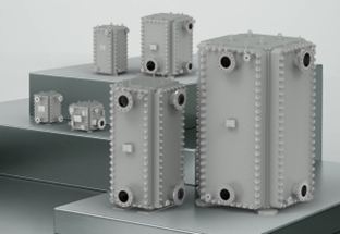
Shanghai Heat Transfer Equipment Co., Ltd. (SHPHE) introduces the HT-Bloc Welded Plate HE. This technology eliminates gaskets entirely, combining high efficiency with durability to solve the industry’s “Efficiency vs. Safety” paradox.
2. Technical Analysis: Why Traditional Designs Fail
To understand the HT-Bloc advantage, it is necessary to analyze the inherent bottlenecks of traditional heat exchangers.
2.1 Shell-and-Tube Limitations
Despite their popularity, Shell-and-Tube designs face systemic inefficiencies:
Laminar Sublayer Resistance: Fluid flow requires high velocities (Re > 2300) to break the laminar boundary layer inside tubes.
Shell-Side Dead Zones: Baffles create “dead zones” and bypass streams where heat transfer is negligible.
Low K-Values: The Overall Heat Transfer Coefficient (K-value) typically ranges from 200–2000 W/m²·K. This requires large surface areas and massive physical footprints to achieve thermal duties.
2.2 Gasketed Plate Limitations
While efficient (K-values up to 7000 W/m²·K), GPHEs are constrained by their sealing mechanism:
Material Failure: Rubber gaskets (EPDM, NBR, FKM) degrade rapidly under high heat or aggressive chemicals (e.g., aromatics, solvents).
Leakage Risk: Thermal cycling causes gasket fatigue, leading to potentially catastrophic leaks in hazardous applications.
3. The HT-Bloc Solution
Against this backdrop, SHPHE’s HT-Bloc Welded Plate HE offers a targeted and comprehensive solution that addresses all the above-mentioned limitations of traditional designs, bridging the gap between tubular robustness and plate efficiency through a revolutionary structural design.
3.1 Core Structure: “Robust Core, Flexible Shell”
Fully Welded Plate Pack: The heat transfer core is laser/plasma welded, forming a gasket-free pressure vessel. It handles temperatures from -50°C to 400°C and pressures from vacuum to 4.0 MPa.
Accessible Frame (4-Side Openable): Unlike fully enclosed shell-and-plate units, the HT-Bloc is equipped with four-side removable panels, enabling mechanical cleaning (e.g., high-pressure water jetting) of flow channels — an essential capability for fouling-prone process services.
3.2 Technology Comparison: HT-Bloc vs. Traditional Units
| Feature | Gasketed Plate HE | Shell-and-Tube HE | SHPHE HT-Bloc |
| Sealing Technology | Rubber Gaskets (Leak Prone) | Welded / Gasketed | Fully Welded (Gasket-Free) |
| Heat Transfer Efficiency | High (K=3000-7000) | Low (K=200-2000) | High (K=3000-7000) |
| Pressure/Temp Limit | < 25 bar / < 180°C | High / High | Vacuum to 40 Bar / -50°C to 400°C |
| Cleanability | Easy (Openable plate Pack) | Difficult (Tube side only) | Accessible (Removable Panels) |
| Footprint | Compact | Massive | Compact (1/4 size of Tubular) |
4. Core Design: Microfluidic Dynamics and Flow Channel Optimization
A key driver of the HT-Bloc’s superior thermal performance is its innovative plate design, which enables precise regulation of fluid flow behavior at the microscopic scale. Leveraging decades of industry expertise and extensive computational fluid dynamics (CFD) simulations, SHPHE has continuously refined the corrugated structure of the heat exchange plates and optimized the overall fluid distribution design.
4.1 Turbulence Enhancement Mechanism of Corrugated Plates
The HT-Bloc plate features a specially formed chevron (herringbone) corrugated structure pressed onto its surface.
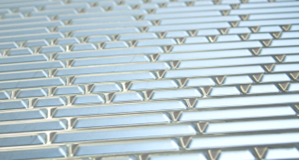
Low Reynolds Number Turbulence: In smooth circular tubes, fluid flow typically transitions from laminar to turbulent regime when the Reynolds number (Re) exceeds 2300. By contrast, within the intricate corrugated flow channels of the HT-Bloc, fluid undergoes constant directional changes, generating intense secondary flow and vortex formation. This triggers turbulent flow at a Reynolds number as low as 1000.
Boundary Layer Disruption: Turbulence not only strengthens radial fluid mixing, but more critically, continuously disrupts the laminar sublayer near the plate wall — the primary source of thermal resistance. Eliminating this thin sublayer results in a sharp rise in the overall heat transfer coefficient, which is typically 3 to 5 times higher than that of shell-and-tube heat exchangers.
Shear Force Self-Cleaning: High-intensity turbulence generates substantial wall shear stress on the plate surface. This shear force effectively scours away fouling particles attempting to adhere to the plate surface, significantly reducing the fouling factor and extending the equipment’s cleaning cycle.
4.2 Flexible Flow Configuration: Counter-Current Flow & Multi-Pass Design
Unlike shell-and-tube heat exchangers, whose flow configurations are fixed and difficult to modify once manufactured, the HT-Bloc offers exceptional engineering flexibility.
Pure Counter-Current Heat Exchange: For multi-pass designs, the HT-Bloc enables true counter-current flow between hot and cold fluids. Counter-current flow is critical for achieving high heat recovery efficiency; it allows the outlet temperature of the cold fluid to exceed that of the hot fluid (known as temperature cross). In water-to-water heat exchange applications, the approach temperature difference can be compressed to within 3℃ .
Asymmetric Flow Design: By installing partition plates within the header assemblies, the HT-Bloc can easily accommodate different pass counts on the hot and cold sides. For instance, a single-pass configuration can be applied to the high-flowrate side, while a multi-pass arrangement is used for the low-flowrate side. This balances flow velocity and pressure drop across both sides, optimizing overall heat transfer performance.
5. Core Manufacturing: Welding Process Control
In the manufacturing of fully welded plate heat exchangers, the welding quality at plate edges directly determines the service life and corrosion resistance of the equipment. There are two mainstream welding methods currently available: lap welding and butt welding. For the production of the HT-Bloc, SHPHE insists on adopting butt welding technology, which features a more complex process but delivers far superior performance.

5.1 Hazards of Lap Welding
Many low-cost all-welded heat exchangers employ lap welding, a process in which the edges of two plates are overlapped prior to welding.
Microscopic Mechanism
This configuration creates microscale crevices in the overlapping zones of the plates.
Corrosion Evolution
In corrosive media such as chloride-containing cooling water, the fluid within the crevice becomes stagnant. As corrosion proceeds, oxygen inside the crevice is rapidly depleted, while the exterior remains oxygen-rich. This results in the metal inside the crevice acting as the anode and the external metal as the cathode, forming active oxygen concentration cell.
5.2 The SHPHE Butt Welding Solution
SHPHE HT‑Bloc adopts advanced plasma or laser welding technology to fuse the plate edges in an edge‑to‑edge manner.
Elimination of Dead Zones:The butt weld is flush with the base material surface, completely eliminating physical crevice structures and preventing crevice corrosion.As fluid flows over the weld surface, continuous scouring is maintained, preventing stagnant zones from forming.This fundamentally cuts off the conditions required for crevice corrosion to occur.
Fatigue Resistance:Under alternating temperature or pressure loading, lap joints exhibit severe stress concentration at the weld root due to geometric discontinuity, which is highly prone to fatigue cracking.In contrast, the stress flow lines of butt welds are smooth and uniform, and their fatigue strength is close to that of the base metal itself.
Reliable Quality:SHPHE’s automated welding production line, combined with strict non-destructive testing (NDT) including penetrant testing (PT) and helium leak testing, ensures the weld penetration and integrity of every weld joint meet nuclear-grade safety standards and satisfy the stringent requirements of ASME U Stamp.
6.Special Operating Condition Solutions
In industries such as papermaking, alumina production and fermentation, process fluids typically contain a large number of fibers, solid particles or crystals. The narrow flow channels (2-5mm) and dense contact points of standard plate heat exchangers are highly prone to clogging. To resolve this issue, SHPHE has developed the HT-Bloc Wide Gap series.
Wide Gap Channel Design: The channel gap ranges from 6mm to 30mm, allowing unobstructed flow of fluids containing large-diameter particles or long fibers.
Special Corrugated Design:
Pillar/Dimpled Pattern: Unlike the point-to-point contact of conventional chevron corrugations, wide gap plates adopt pillar or dimpled supports, which drastically reduce the number of contact points and eliminate anchoring points for fiber entanglement, ensuring smoother fluid flow.

Free Flow Design: For extremely dirty and fouling-prone fluids, SHPHE offers a free flow design with zero or minimal contact points, completely eliminating the risk of clogging.
Typical Applications
Alumina Industry: Handles spent liquor and red mud slurry. The wide gap design enables the passage of high solid-content slurry while maintaining high heat transfer efficiency, replacing bulky and inefficient shell-and-tube or spiral plate heat exchangers.
Papermaking & Fermentation: Treats fiber-containing black liquor and fermentation mash. The fully welded structure prevents odor leakage, while the wide flow channels avoid fiber adhesion and clogging on the plate surface.
Crude Oil Cooling: Used as a crude oil cooler, the wide gap design effectively resists sediment and wax deposition in crude oil. Coupled with the detachable frame, mechanical cleaning becomes simple and feasible.
7. Quality Assurance & Lifecycle Value
SHPHE HT-Bloc is designed and manufactured in strict compliance with international standards:
Design Standards: API 662 / ISO 15547 (petrochemical and natural gas plate heat exchanger standards) and ASME Section VIII Div. 1 pressure vessel code.
Certifications: ASME U Stamp, NB Registration, EU CE (PED) certification, plus third-party approvals from BV and SGS.
Inspection Protocol: Every unit undergoes rigorous non-destructive testing (NDT) — including radiographic testing (RT), penetrant testing (PT) and hydrostatic pressure testing before delivery.
Total Cost of Ownership (TCO)
Focusing on Lifecycle Cost (LCC) rather than just CAPEX reveals the HT-Bloc’s true value:
Reduced CAPEX: High efficiency means less surface area. Even with high-grade materials (Titanium, Hastelloy), the total cost is often lower than bulky Carbon Steel tubular units.
Lower OPEX: Compact size reduces installation and civil costs. High heat recovery cuts energy bills. Accessible design minimizes maintenance downtime.
8. Conclusion:Technological Upgrade for Process Industry
The HT-Bloc is more than just a replacement for traditional heat exchangers, it represents a targeted technological upgrade for the global process industry, perfectly aligning with the industry’s pursuit of carbon neutrality and operational excellence.
HT-Bloc combines the exceptional safety of a fully welded core with the easy maintainability of a detachable frame. Through optimized flow channel design and precise control of butt welding technology, SHPHE HT-Bloc eliminates corrosion and fouling risks at the source.
For refineries, chemical plants and power stations pursuing carbon neutrality goals and operational excellence, HT-Bloc stands as the optimal choice, striking the perfect balance between thermal performance and long-term, secure operation.
Appendix: Technical Specifications
|
Parameter |
Specification |
| Max Area per Unit | 900 m² |
| Plate Thickness | 0.8-2.0 mm |
| Design Pressure | Vacuum to 4.0 MPa (40 bar) |
| Design Temperature | -50°C to +400°C |
| Plate Materials | 304/304L,316/316L, 904L, 254SMO, Hastelloy C-276, Titanium |
| Connection Size | DN25 to DN1000 |
| Certifications | ASME U, NB, CE, BV, CCS, SGS, ISO 9001 |
Post time: Mar-23-2026