

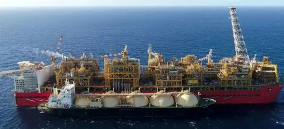
Floating Liquefied Natural Gas (FLNG) facilities serve as the core equipment for the development of deep-sea natural gas resources. By integrating the entire onshore natural gas processing flow onto a mobile offshore platform, FLNG enables the integrated operation of natural gas covering extraction, purification, liquefaction, storage, and offloading.
1. Core Process Flow of FLNG Platforms
The primary process flow of an FLNG platform can be refined into five critical stages:
1) Feed Gas Extraction and Transport
Raw natural gas is extracted from deep-sea wells via subsea trees and transported to the FLNG platform through subsea flowlines. The feed gas typically arrives at an initial pressure of 1–10 MPa, with temperatures ranging from 4 to 12 °C, depending on the subsea environment.
2) Feed Gas Pre-treatment
To prevent corrosion, freezing/blockage, and reduced liquefaction efficiency in downstream equipment, the gas undergoes rigorous purification:
- Amine Scrubbing: For decarbonization (CO2 removal).
- Alcohol-Amine Process: For desulfurization (H2S removal).
- Molecular Sieve Dehydration: For removing water, trace heavy hydrocarbons, and mercury.
- Target Specifications: CO2 < 50 ppm, H2S < 6 mg/m³, and H2O ≤ 1 ppm.
3) Natural Gas Compression
Multi-stage centrifugal compressors boost the purified natural gas pressure to 4–10 MPa required for liquefaction. Due to the adiabatic compression effect, gas temperatures rise to 80–120°C, necessitating cooling via heat exchangers before the next stage.
4) Natural Gas Liquefaction
This is the heart of the process. Using the Mixed Refrigerant Cycle (MRC), a mixed refrigerant (comprising methane, ethane, propane, nitrogen, etc.) is compressed, cooled, and throttled to create a cryogenic source. This refrigerant exchanges heat efficiently with high-pressure purified natural gas in the liquefier, cooling the gas to -162°C at atmospheric pressure. This phase change transforms it from gas to liquid LNG, reducing its volume to approximately 1/600 of the original.
5) LNG Storage and Offloading
The liquefied LNG is stored in the platform’s built-in cryogenic adiabatic tanks, maintained at -162°C and 0.1–0.2 MPa. It is then transferred via loading arms to LNG carriers, achieving the offshore export of deep-sea natural gas resources.
2. Challenges for Heat Exchangers in FLNG Applications
FLNG platforms operate in harsh offshore environments, imposing strict demands on core heat transfer equipment:
- With limited deck space and load capacity, FLNG layouts are highly compact.
- High salt spray, high humidity and marine atmospheric corrosion demand superior corrosion resistance and fatigue strength for heat exchangers.
- Core processes such as natural gas liquefaction and BOG (Boil-Off Gas) recovery require efficient heat transfer. The presence of gas-liquid two-phase flow during heat exchange imposes high requirements on thermal efficiency and flow field stability.
- FLNG operations require high continuity and safety, which necessitates heat exchange equipment with long-term stable operation capability and convenient maintenance.
3. Advantages of PCHE
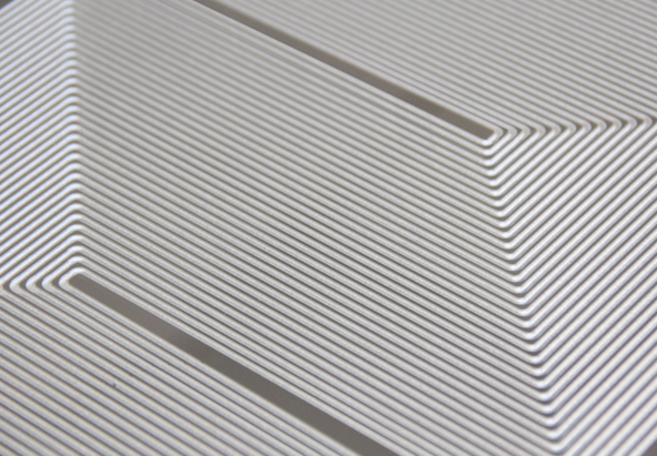
1) Superior Compactness: Utilizing micro-channel structures with millimeter-scale flow passages, PCHE achieves a heat transfer area density of up to 2500 m²/m³. Efficiency is 3–5 times higher than traditional shell-and-tube exchangers, while volume and weight are reduced to 1/10th and 1/5th respectively, effectively solving space and load constraints.
2) Excellent structural strength, corrosion resistance, and fatigue resistance. PCHE is made of stainless steel or nickel-based alloy, and its core is formed by the integral diffusion welding process, with strength reaching 95% of the base metal and no risk of weld leakage. The material itself has good resistance to marine salt spray corrosion, and the integrated structure can effectively withstand alternating loads and impact vibrations, so its fatigue life is significantly better than that of traditional heat.
3) Strong adaptability to working conditions. The microchannel design can flexibly adapt to gas-liquid two-phase flow, a wide temperature range (-196°C to +850℃), and a wide pressure range (0.1–100 MPa). In heat exchange scenarios such as cryogenic liquefaction and BOG recovery, it has the advantages of uniform temperature, low flow resistance, and outstanding heat exchange stability.
4) Convenient operation and maintenance. PCHE adopts a modular design, which can be flexibly combined according to process requirements, with convenient installation and disassembly, which can greatly reduce the operation and maintenance costs and shutdown risks of FLNG offshore platforms.
4. Application of PCHE on FLNG Platforms
Due to its technical characteristics, PCHE has become the optimal choice for multiple critical heat transfer units on FLNG platforms.
Shanghai Heat Transfer Equipment Co., Ltd. (SHPHE) solutions are widely applied in the following critical positions:
1) Natural Gas Cooler (Feed Gas Pre-treatment)
- Function: Cools raw gas to stabilize conditions for purification.
- Cold Side: Seawater (15–35°C, 0.1–0.5 MPa).
- Hot Side: Raw Natural Gas (Inlet: 40–60°C, Outlet: 20–40°C, 1–5 MPa).
2) Compressor Aftercooler (Compression Stage)
- Function: Removes adiabatic heat generated during compression.
- Cold Side: Seawater (15–35°C, 0.1–0.5 MPa).
- Hot Side: Compressed Natural Gas (Inlet: 80–120°C, Outlet: 30–40°C, 5–10 MPa).
3) Natural Gas Liquefier (Core Liquefaction Stage)
- Function: Serves as the core equipment for converting high-pressure gas into LNG.
- Cold Side: Mixed Refrigerant (-100 to -162°C, 1–5 MPa).
- Hot Side: Purified High-Pressure Gas (Inlet: 20–40°C, Outlet: -162°C, 4–10 MPa).
4) BOG Heat Exchanger (Storage & Recovery Stage)
- Function: Re-liquefies Boil-Off Gas (BOG) using LNG cold energy to reduce loss and emissions.
- Cold Side: LNG (-162°C, 0.7–2 MPa).
- Hot Side: BOG Gas (-10 to 20°C, 0.5–4 MPa).
5) High-Pressure (and Low-Pressure) Vaporizer
- Function: Regasifies LNG to platform power and instrumentation fuel.
- Cold Side: LNG (-162°C, 0.1–0.2 MPa).
- Hot Side: Seawater/Air/Glycol Water (5–25°C, up to 10 MPa for high-pressure types).
The PCHE products manufactured by Shanghai Heat Transfer Equipment Co., Ltd. adopt advanced diffusion bonding forming technology, strictly control the micro-channel dimension accuracy and manufacturing process to ensure the structural strength and performance. The products can stably withstand a pressure of 100 MPa and extreme temperatures (-196°C to +850°C), adapting to the cryogenic and high-pressure working conditions of FLNG. To address uneven heat transfer in gas-liquid two-phase flows, Shanghai Heat Transfer Equipment Co., Ltd. (SHPHE) optimizes the flow channel structure design through numerical simulation (CFD), adopts a special-shaped micro-channel layout, which effectively improves the heat transfer uniformity of gas-liquid two-phase flow, reduces flow resistance and pressure drop loss, and enhances heat transfer efficiency.
PCHE Product Parameters of Shanghai Heat Transfer Equipment Co., Ltd. (SHPHE)
- Max Design Pressure: 100 MPa
- Design Temperature: -196°C ~ 850°C
- Heat Transfer Area: Up to 8000 m²
- Plate Thickness: 0.4 ~ 4 mm
- Channel Width: 0.4 ~ 4 mm
- Materials: 304, 316L, Duplex 2205, TA1 (Titanium), High-Temperature Alloys.
Post time: Mar-06-2026